
Electric train staff instruments
Following on from the invention of the electric train tablet in 1880, the electric train staff was developed in 1888 by the L&NWR and licensed to the Railway Signal Co. This company had been formed by an ex-employee of the L&NWR, one George Edwards, who had started his work on signalling with Saxby & Farmer, had left them in 1873 to become the signalling superintendent of the L&NWR, left them in 1876 to join the Gloucester Wagon Co. when they decided to diversify into signalling and who finally set up his own company, the Railway Signal Co., in 1881. Not surprisingly, he obtained a large number of contracts from the L&NWR which led to the Railway Signal Co. becoming probably the most successful signalling contractor in the 1890s.
The function of the electric train staff is simple, by means of having an instrument at each end of a block section, electrically interlocked, just one staff at a time can be withdrawn (from either end) and given to the driver as his authority, in conjunction with the correct signals being off, to go on the single line. The staffs are made with five rings which coincide with slots in the instrument, four of them at a set spacing whilst the fifth is set at a different spacing from the instruments for the sections on either side, thus preventing the staff for one section being put in the instrument for another section. They all carry the names of the block posts at either end of the section, and are painted in different colours and distributed so that no one colour can ever apply to the staffs of adjacent sections.
The staffs are kept in the slot in the lower part of the Instrument and when one is required, it is lifted to the top and, provided a release is being given by the signalman at the other end, the relay will allow the cam inside to rotate thereby permitting the staff to be withdrawn.
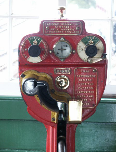
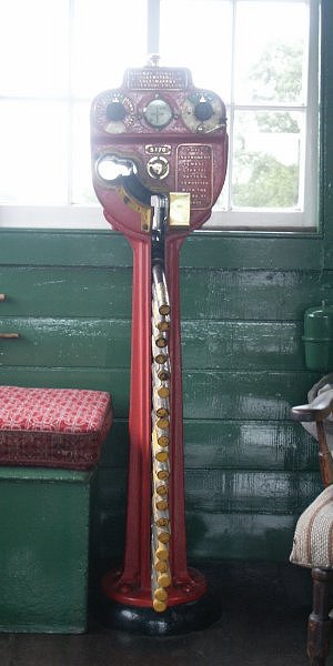
These Instruments gave long and faithful service on the Bluebell, in use between Sheffield Park and Horsted Keynes, until being replaced by Key Token Instruments (see below) at the end of 2004. They are being kept, however, with the eventual aim of being used on a future Horsted Keynes to Ardingly section.
The method of use as practised on the Bluebell is as follows:
- “A” and “B” represent the Signal boxes at either end of a block section. Prior to the despatch of a train from “A” the signalman there, provided all other criteria have been met to send a train, must send the appropriate “Is Line Clear” signal to the signalman at “B”. Assuming the signalman at “B” is able to accept the train, having replied to “A’s” bell signal “B” will hold down his release key until the galvanometer needle, which will be deflected, returns to the upright position, indicating that a staff has been withdrawn at “A”.
- When the signalman at “A” sees his galvanometer needle deflect he must point his right-hand indicator to “For Staff” and take out a staff which will mechanically repoint his right-hand indicator to “For Bell”. As soon as “A” has taken out a staff he must turn the pointer on his left-hand indicator to “Down Staff Out” if it is a down train, or “Up Staff Out” if it is an up train. “B” must also turn his left-hand indicator to “Up Staff Out” or “Down Staff Out” as the case may be.
- The signalman at “A” will then lower his signals for the train to leave and hand the staff to the driver. Once he has lowered his advanced starting signal he cannot replace it and lower it again without replacing the staff in his instrument and obtaining another release from “B”.
- On arrival of the train at “B” the signalman there must obtain the staff from the driver and, after replacing his signals and checking that the train is complete, insert it in his instrument and give “A” the “Train Out of Section” signal which must be acknowledged. Both “A” and “B” must now repoint their left-hand indicators to “Staff In”.
- Should it be necessary to replace a staff in the instrument from which it was withdrawn, then the “Cancelling” signal must be sent to the signalman at the other end of the section, and acknowledged.
It is frequently the case on other railways that the Release Key is also used for belling (hence the “For Bell” position), but in the case of the Bluebell a separate bell plunger is used.

Electric key token instruments
The origins of the electric key token lie in the electric train tablet system that was originally developed in 1880 by Tyer & Co. in conjunction with the Caledonian Railway. The function was simple, by means of having an instrument at each end of a block section, electrically interlocked, just one tablet at a time could be withdrawn (from either end) and given to the driver as his authority, in conjunction with the correct signals being off, to go on the single line. Early tablets were in the main round (there were some square ones used for long section purposes) with a varied number and position of notches so that the tablet for one section could not be put in the instrument for the adjacent section. Later versions had a single notch in a standard location, but a varying shape was used.
This was followed by the electric train Staff of 1888 and then, in 1912, the Great Western Railway developed the electric key token, licensed to Tyer & Co., which used a smaller token, operated in the instrument in the same manner as a key in a lock. Once again, provision was made to prevent the possibility of a token being put in the wrong instrument, this time by means of a slot in the key quadrant although some special purpose tokens had two slots. To assist with visual identification, the handles are made in four different shape/colour combinations with no two adjoining sections having the same shape/colour.
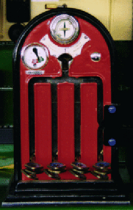

The Bluebell uses Key Token Instruments between Sheffield Park and Horsted Keynes, between Horsted Keynes and Kingscote, between Kingscote and East Grinstead and, now that the re-signalling of Horsted Keynes is complete and the Signalbox there can be switched out of circuit, for a “long” section from Sheffield Park to Kingscote.
The method of use as practised on the Bluebell is as follows:
- “A” and “B” represent the Signalboxes at either end of a block section. Prior to the despatch of a train from “A” the signalman there, provided all other criteria have been met to send a train, must send the appropriate “Is Line Clear” signal to the signalman at “B”.
- Assuming the signalman at “B” is able to accept the train, having replied to “A’s” bell signal “B” will hold in his plunger until the galvanometer needle, which will be deflected, momentarily returns twice to the upright position, indicating that a token has been withdrawn at “A”. “B” must then immediately release his plunger.
- When the signalman at “A” sees the galvanometer needle deflect he must place a key-token on the pin and give it two half turns to the left which set his indicator to the “Train Going To” position. The key-token can then be withdrawn from the instrument. When the galvanometer needle has again returned to the upright position after “B” has released his plunger, “A” must plunge to “B” which will change “B’s” indicator to the “Train Coming From” position.
- The signalman at “A” will then lower his signals for the train to leave, place the key-token in a leather pouch and hand it to the driver. Once he has lowered his advanced starting signal he cannot replace it and lower it again without replacing the key-token in his instrument and obtaining another release from “B”.
- On arrival of the train at “B” the signalman there must obtain the key-token from the driver and, after replacing his signals and checking that the train is complete, deposit it in his instrument by placing it on the pin and giving it two half turns to the right.
- He must then plunge to “A” which will change “A’s” indicator to the “Line Normal” position and give “A” the “Train Out of Section” signal which must be acknowledged by “A” who must then plunge to “B” to re-set “B’s” indicator to “Line Normal”. Should it be necessary to replace a key-token in the instrument from which it was withdrawn, then the “Cancelling” signal must be sent to the signalman at the other end of the section, and acknowledged.
It is frequently the case on other railways that the Release Plunger is also used for belling, but in the case of the Bluebell a seperate bell plunger is used.

The Walker’s Train Describer
The Walker’s Train Describer consists of a clockwork driven mechanical “Sending” instrument and an electro-mechanical “Receiving” instrument. Each of these instruments has an identical dial upon which is fixed tablets showing various required destinations and a pointer to indicate the tablet required. The “Sending” instrument, which has a lever adjacent to each of the tablets, is located by the Loco Yard ground frame and the “Receiving” one is in the Signal box.
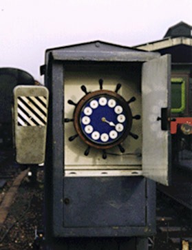
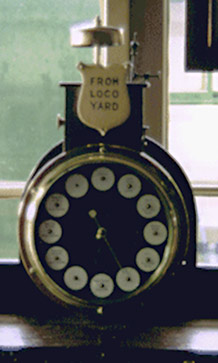
When the running foreman (or other authorised person) needs to send a request to the signalman for a particular move to be set up he has to carry out the following procedure:
- First he will need to pull towards himself the lever adjacent to the appropriate tablet and then he has to push away from himself the lever by which the pointer is currently resting. The pointer will now run around the dial until it reaches the lever that was pulled and then remain in that position.
- The “Receiving” instrument in the Signal box will step on in unison with the “Sending” instrument whilst a bell will sound one beat as it reaches each tablet. If the destination tablet occurs less than five points from where the pointer is resting then the mechanism and pointer must be allowed to travel a complete circuit of the dial to the “new” description. To do this the levers are worked in the opposite order so that the lever adjacent to the appropriate new description is pulled out after the pointer has passed that description.
- Upon receipt of a destination (other than “Cancel”) the signalman must acknowledge the receipt by sending five beats on the appropriate bell key regardless of whether or not he is in a position to make the described movement. Upon receipt of the “Cancel” indication, the signalman will acknowledge this by one beat on the appropriate bell key.
As with all things mechanical, it does sometimes happen that the two instruments can become out of phase. In this situation the instrument should not be used until such time as an engineer from the S&T Department has corrected it.


